I have cut spur gears on hobbing machines for more than fifteen years. The first question I ask when an RFQ lands on my desk is not about material or hardness. It is about tooth size. Module is the metric unit that defines tooth size, and it drives pitch diameter, cutting force, tooling inventory, and final unit cost. If the drawing leaves the module implicit or uses a non-standard value, three suppliers will quote three different assumptions. I have seen the same gear spec quoted with a 40% spread because nobody confirmed whether the part needed m1.0 or m1.25.
This guide covers gear hobbing module selection for spur gears. It explains what the module value means, how to convert from diametral pitch, where tooth count creates undercut problems, and how to read a hob module chart. I will keep the focus on the decisions that affect your quote and your assembly fit.
What gear module really means
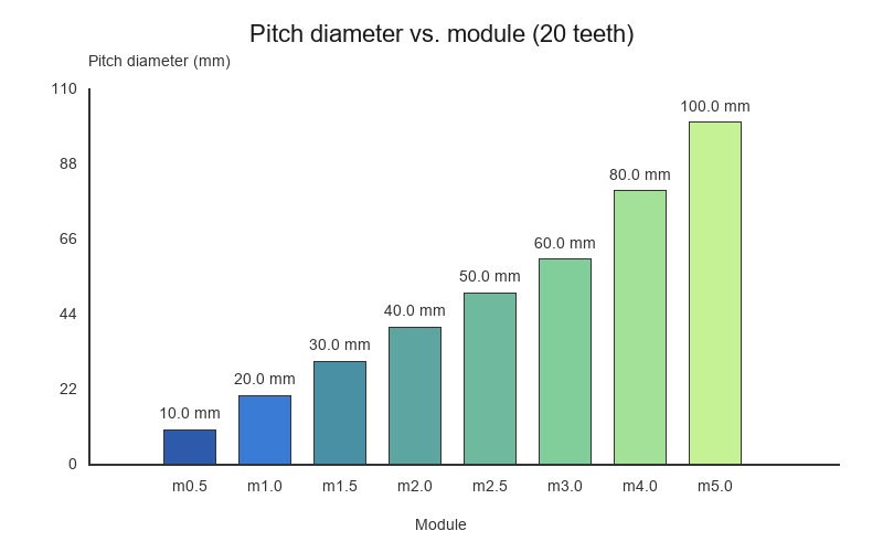
Module (m) is pitch diameter in millimeters divided by tooth count. A 20-tooth gear with m1.0 has a 20 mm pitch diameter. The same tooth count at m2.0 is 40 mm. Outside diameter is roughly pitch diameter plus two times the module. That means this single number sets nearly every major dimension.
Tooth geometry also follows from the module. The addendum equals one module. The dedendum is 1.25 modules for standard full-depth teeth. Whole depth is 2.25 modules. These numbers are not negotiable; they are built into the hob cutter. Change the size and you change the cutter.
Cutting time also scales with tooth size. An m2.0 gear removes roughly four times the chip volume of an m1.0 gear per tooth. The machine load, coolant flow, and cycle time all scale with that number. That is why the module is one of the first inputs in our quoting model.
I keep a small set of standard hobs in our shop: m0.5, m0.8, m1.0, m1.5, m2.0, m2.5, m3.0, m4.0, and m5.0. A custom value means a custom hob, which means six to eight weeks of toolmaking and a cost that can exceed the first production run. That is why I push buyers toward standard values unless the application truly needs something else.
If you are unsure whether your part fits hobbing at all, our CNC machining service is often a faster way to prove prototypes before you commit to a hob. For very small complex metal parts, metal injection molding can be an alternative when gears merge with housings or levers.
How to pick a module for strength and clearance
Good gear hobbing module selection balances strength, envelope, and tooling cost. I usually run the decision in three steps: torque, fit, then clearance. Skip one and the gear either breaks or does not fit in the box.
Start with the torque path. Larger teeth carry more load because the tooth cross-section grows with the size. An m2.0 tooth is roughly four times the bending area of an m1.0 tooth, not twice. The relationship is square, not linear. If you are transmitting power, start with a larger size than you think.
Then check the envelope. A larger size also means a larger outside diameter for the same tooth count. In a gearbox with tight center distance, you may need more teeth at a smaller pitch to hit the ratio without moving shafts. I have redesigned a 16-tooth m2.0 pinion into a 24-tooth m1.5 pinion to keep the same center distance. The tooth strength dropped, but the assembly fit.
Material matters too. 4140 steel at 32 HRC can use a slightly smaller size than 316L stainless steel at 95 HRB because steel carries higher contact stress. Hardened gears after cutting and heat treat often need stock allowance for grinding. That allowance is easier to hold on larger teeth.
Clearance is the last filter. The tip of one gear must not scrape the root of the mating gear. Standard 20° pressure angle gears give adequate clearance when both gears use the same size and standard addendum. If you profile-shift a pinion to avoid undercut, recheck clearance. I have seen shifted pinions bind because the mating gear was drawn with a stock center distance.
Module conversion when your drawing uses diametral pitch
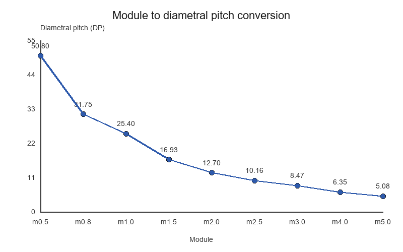
North American drawings often specify diametral pitch (DP) instead of module. The conversion is simple: m = 25.4 / DP. But the result is rarely a standard metric value, so you have to choose the closest practical one.
DP 24 gives m1.058. We would normally cut m1.0 and adjust the tooth count or center distance to recover the ratio. DP 16 gives m1.5875, which is close enough to m1.5 for most applications. DP 32 gives m0.79375; we often move to m0.8.
The conversion gets harder at coarse pitches. DP 8 is m3.175. m3.0 gives a 5.5% smaller tooth, which changes center distance. DP 5 is m5.08, close to m5.0. For high-precision gearboxes, that small difference matters, and you may need a custom hob or a revised drawing.
I always ask buyers to confirm which system governs inspection. If the drawing shows DP but the CMM report is in metric module, the conversion rounding can hide a rejection. State the value clearly on the revised drawing and inspect to that value.
Tooth count and hob module limits to watch
The biggest mistake I see in gear hobbing module selection is ignoring undercut. Standard 20° full-depth hobs undercut pinions with fewer than 17 teeth. The tool tip removes material below the involute, weakening the tooth and adding noise. For 12 to 16 teeth, use positive profile shift. For fewer than 12 teeth, consider a different process or a modified tooth form.
Small sizes have their own limits. m0.3 and below need rigid machines, fine-pitch hobs, and often carbide tooling. Runout and hob sharpening errors show up as profile mistakes. I generally avoid m0.3 unless the annual volume justifies the tooling risk.
Large sizes also have limits. Most shop hobbing machines top out around m6.0 or m8.0. Above that, you move into roughing and shaping territory. The hob itself becomes heavy and expensive. If your gear needs m10, ask whether a forged blank with finish hobbing or shaping makes more sense.
A practical gear hobbing module chart
Use the chart below as a starting point, not a rulebook. The ranges assume steel or stainless steel with standard 20° pressure angle.
| Module | Approx. DP | Typical OD range | Common use |
|---|---|---|---|
| 0.5 | 50 | 6-25 mm | Small actuators, electronics |
| 0.8 | 32 | 10-40 mm | Medical devices, instruments |
| 1.0 | 25 | 12-60 mm | Automotive auxiliary drives |
| 1.5 | 16 | 20-100 mm | Industrial gearboxes |
| 2.0 | 12 | 30-150 mm | Power transmission |
| 2.5 | 10 | 40-200 mm | Heavy machinery |
| 3.0 | 8 | 60-250 mm | Mining, marine |
| 4.0 | 6 | 80-350 mm | Large reducers |
| 5.0 | 5 | 100-450 mm | Heavy reducers, cranes |
Brass and aluminum can use smaller sizes for the same load because the material is softer. Hardened gears after heat treat often need one size larger than the chart suggests to leave grinding stock.
Frequently asked questions
What is the difference between module and diametral pitch?
Module is metric: pitch diameter in millimeters divided by tooth count. Diametral pitch is imperial: tooth count divided by pitch diameter in inches. They describe the same tooth size in different units. Convert with module = 25.4 / DP.
How do I choose module for a high-torque gear?
Start with a larger size than the envelope suggests. Tooth bending strength scales roughly with the square of the module. Then check center distance, mating gear clearance, and whether heat treatment needs grinding stock.
What is the smallest module you can hob reliably?
In most job shops, m0.5 is practical. m0.3 is possible but needs rigid machines, sharp carbide hobs, and high volumes to justify tooling risk. Below that size, consider alternative processes.
Why does my small pinion have undercut?
Standard 20° full-depth hobs undercut pinions below 17 teeth. The hob tip cuts away involute profile near the root. Use positive profile shift for 12 to 16 teeth, or redesign with more teeth.
Can you change module without changing center distance?
No, not if the tooth count stays the same. Center distance equals the sum of pitch diameters divided by two, and pitch diameter depends on tooth size and tooth count. To keep center distance, change tooth count or accept a ratio shift.
Related reading:
- CNC machining vs gear hobbing for prototype gears
- Gear hobbing vs gear shaping differences
- How to choose a metal parts manufacturing process
For tolerance and inspection questions, see our FAQ. For our typical quoting flow, read how we work.
Need Precision Metal Parts for Your Project?
Yujiaxin Tech specializes in MIM, CNC Machining, Powder Metallurgy, Investment Casting, and Gear Hobbing. Get a free quote within 24 hours.