I have quoted powder metallurgy parts for more than fifteen years. The fastest way to ruin a good PM program is to copy a CNC-machined design straight into a sintered-metal tool. I have seen buyers slash unit cost by half after a thirty-minute drawing review, and I have watched others burn through three tool reworks because someone refused to add a radius. The difference is almost always geometry.
Powder metallurgy is a net-shape process. You press metal powder into a die, sinter it below the melting point, and get a part that is close to finished. The closer the as-sintered shape is to the final part, the less machining, grinding, and sizing you need. Every design decision either moves the part toward that net-shape ideal or away from it, and the cost follows quickly.
Keep wall thickness uniform
Thick sections and thin sections in the same part sinter at different rates. The thick area contracts more, pulls on the thin area, and leaves you with cracks, distortion, or oversized dimensions that need machining to fix. I have seen a 6 mm flange next to a 1.5 mm wall pull the whole part out of round by 0.15 mm during sintering.
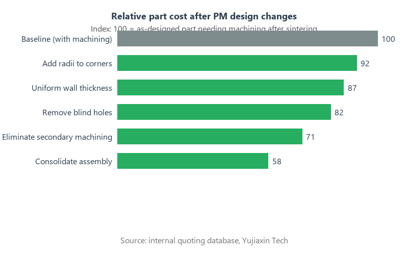
The fix is usually simple. Move material out of the thick section or add ribs to the thin one. Aim for wall thickness ratios no larger than 2:1 within the same part. If you must have a thick boss, core it out. A hollow boss sinter more evenly than a solid one, and the powder savings drop the material cost by 10% to 20%.
Uniform walls also protect the die. Uneven compaction loads concentrate stress on one corner of the tool and shorten its life. We track tool life in hundreds of thousands of parts on well-designed jobs. On jobs with thick bosses and thin webs, we sometimes get half that before a crack opens in the die insert.
Add radii to internal corners
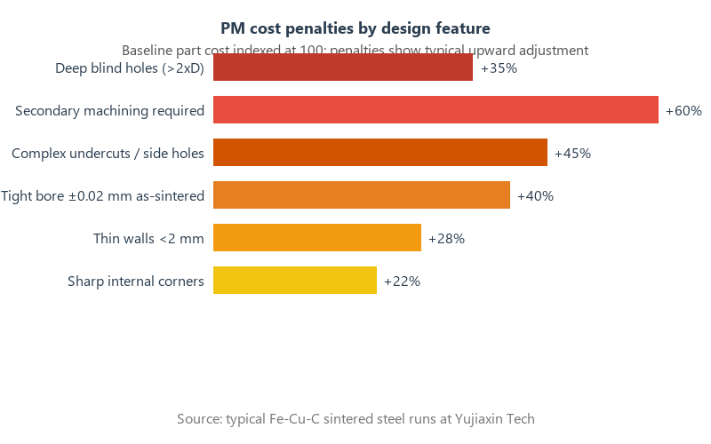
Sharp internal corners are enemies of a PM tool. The punch needs to fill a dead corner with powder, the green part is fragile there, and the die itself becomes a stress concentrator. I always recommend a minimum internal radius of 0.3 mm to 0.5 mm. That small radius improves powder flow, reduces ejection force, and often doubles the life of the punch tip.
External corners matter too. A radius on an outside edge is easier to press and eject than a sharp 90-degree edge. It also reduces the chance of cracking during sintering. If the mating part truly needs a sharp corner, add a secondary machining operation for just that edge instead of making the whole geometry unfriendly to the die.
Buyers sometimes push back because a radius changes the look of the part. I remind them that a broken punch in the middle of a 200,000-piece run changes the look of the lead-time schedule more. Radii are cheap insurance.
Design away from secondary machining
Secondary operations are where PM savings disappear. Drilling a cross-hole, turning a shoulder, or grinding a bore after sintering adds the same machine-shop rates that PM was supposed to avoid. The goal is to design the part so the press and sinter steps yield a usable component.
Threaded holes are a classic example. PM can hold threads in the die, but they add cost and reduce tool life. A self-tapping thread in a straight sintered hole is usually cheaper for assemblies up to a few hundred thousand pieces. If you must have machine threads, keep them in a location where a simple secondary drilling and tapping station can reach them without a fixture.
Undercuts and side holes are even worse. PM presses compact from the top and bottom. Any feature that needs lateral powder movement needs a side action, a split die, or a secondary machining step. Those are not always deal-breakers, but each one adds tooling cost and cycle time. I treat every side hole as a $2,000 to $5,000 question.
Rethink blind holes and deep slots
Blind holes in PM trap air and create density gradients. The powder at the bottom of a deep hole does not compress as well as the powder at the top, so the hole ends up shallow or the surrounding wall ends up porous. We normally limit blind holes to a depth no more than two times the diameter. Deeper than that, and we drill them after sintering.
Deep narrow slots have the same problem. The punch has to slide between two thin die walls, and those walls wear quickly. Slots wider than 1.5 mm and shorter than three times their width are usually safe. Anything tighter moves into EDM die-work territory, and EDM work in a PM die is expensive.
Through-holes are much friendlier than blind holes. They let air escape and give the powder a clear compaction path. If a blind hole is not functionally necessary, convert it to a through-hole. It usually saves both tooling and inspection time.
Relax tolerances where function allows
PM parts hold excellent tolerances on dimensions that run perpendicular to the pressing direction, typically ±0.05 mm to ±0.1 mm per 25 mm. Tolerances along the pressing direction are harder because density gradients affect length. As-sintered tolerances of ±0.25 mm to ±0.5 mm per 25 mm are common there.
When a print calls for ±0.02 mm on a sintered bore, we usually end up sizing or grinding it. That single callout can double the part cost. I always ask which surfaces actually mate with something, and whether a looser tolerance plus a secondary operation on just that surface is cheaper than sizing the whole part.
Geometric tolerances matter too. True position callouts of 0.05 mm on holes pressed from opposite ends are optimistic without a sizing operation. We can hit them, but the customer pays for the extra step. A 0.1 mm true position on the same feature is often free.
Match the material to the volume
Material selection is a volume game. Plain iron-copper-carbon mixes are the workhorses of the PM industry. They press well, sinter predictably, and cost less per kilogram than stainless or brass powders. For automotive brackets, lock components, and structural parts at 50,000 pieces per year and up, Fe-2Cu-0.6C is usually the right starting point.
Stainless steel 316L and 17-4PH powders cost two to three times more than plain iron mixes. They make sense when corrosion resistance or magnetic properties are non-negotiable. I have moved customers back to plated plain steel when the real requirement was just a salt-spray test, and the cost drop was 40%.
Pre-alloyed powders cost more than diffusion-alloyed or admixed powders, but they give better consistency. For high-volume parts with tight mechanical property windows, the extra powder cost is worth it because it reduces scrap. At low volumes, admixed powders keep tooling simpler and unit cost lower.
Consolidate assemblies into one part
This is where PM pays off most dramatically. A bracket, a bushing, and a spacer that are currently three stamped or turned pieces can often become one pressed part. The assembly labor, fasteners, and tolerance stack-up disappear. I have seen consolidated parts cut total installed cost by 50% even when the single PM part costs more than any one of the original three.
Consolidation works best when the three pieces share a common pressing direction. If the assembly has features pointing in three different directions, the die becomes a puzzle and the savings evaporate. Start by looking for parts that stack along one axis. Those are the easy wins.
One warning: do not consolidate for the sake of consolidation. A single complex PM part with side actions can cost more than the assembly it replaces. We model both options before committing. Sometimes the assembly stays.
Use draft angles and flat lands
PM parts need to eject from a rigid die. A straight wall with no draft binds against the die walls and can crack during ejection. A one-degree draft on vertical walls is usually enough. On tall parts, two degrees is safer. If the mating part needs a straight wall, reserve the straight section for a short sizing or machining step.
Flat lands on bearing surfaces are easier to hold than curved ones. A flat seat pressed to size is almost free. A curved surface that needs grinding is not. I always encourage designers to use flat contact faces whenever the assembly allows it.
Chamfers are also easier than radii on some edges, and they help with assembly alignment. A 0.2 mm by 45-degree chamfer on a bore entry removes burrs without adding a deburring step.
Frequently asked questions
How much does a powder metallurgy part cost per part?
A simple Fe-Cu-C steel part in volumes above 10,000 pieces often costs $0.15 to $0.60 per part as-sintered. Add secondary machining and the range moves to $0.40 to $2.00. Stainless steel or complex geometries start higher.
What is the typical tooling life expectancy in powder metallurgy?
Well-designed parts run 300,000 to 1,000,000 shots on a single set of carbide or tool-steel dies. Parts with thin webs, sharp corners, or deep holes can wear dies out in 100,000 to 200,000 shots.
Which secondary operations add the most cost?
Machining, drilling, grinding, and heat treating add the most. Sizing, repressing, and oil impregnation are lower-cost steps that often improve the part rather than just finishing it.
Can PM hold ±0.025 mm tolerances?
Yes, but usually only after sizing or machining. As-sintered tolerances of ±0.05 mm to ±0.1 mm are more realistic for most dimensions.
Is powder metallurgy economical for small runs?
Runs below 5,000 to 10,000 pieces often struggle to amortize die cost. At very low volumes, CNC machining or metal injection molding is usually cheaper.
Related reading:
Need Precision Metal Parts for Your Project?
Yujiaxin Tech specializes in MIM, CNC Machining, Powder Metallurgy, Investment Casting, and Gear Hobbing. Get a free quote within 24 hours.