Titanium Medical Implant Cavity Parts
Medical Device Components
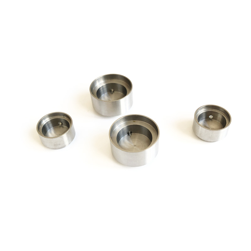
Titanium implant cavity parts machined on five axis equipment in Ti-6Al-4V ELI, with graft windows, housing bays and mating pockets held to plus or minus 0.02 mm and passivated to ASTM F86.
| Category | Medical Device Components |
| Materials | Ti-6Al-4V ELI, Ti-6Al-4V Grade 5, Ti-6Al-7Nb, CP Titanium Grade 2, CP Titanium Grade 4 |
| Industries | Medical Devices, Orthopedics, Dental, Implantable Devices |
Send your drawing or 3D model — engineering review and quotation within 24 hours.
What a titanium implant cavity part is
An implant cavity is the machined pocket that either holds something inside an implant or receives a mating component. A spinal cage with a graft window, a dental abutment with an internal screw seat, a titanium housing with a sealed electronics bay, an acetabular shell with a liner recess: each is judged on cavity geometry, wall section and surface state rather than on outside appearance.
We machine titanium implant cavity parts from bar and forging stock on five axis equipment, with the cavity held inside a stated band and the surface left in a condition that passivation can accept. This page covers the geometry limits, the grades we hold certificates for, and the points where a drawing usually needs to change before a cavity can be cut reliably.
Three families, three different risks
Implant cavities reach our shop in three shapes, and each one puts the manufacturing risk somewhere else.
- Graft and insert cavities hold bone graft, a drug carrier or a polymer insert inside a load bearing implant. Volume, rim flatness and the absence of sharp internal corners decide whether the graft packs evenly and whether the cavity root becomes a crack origin.
- Housing cavities enclose electronics or a mechanism, so they need a sealing land at the rim and enough wall stiffness that the lid does not lift. Flatness at the land matters more than nominal depth.
- Mating pockets receive a second component, a screw seat or a taper junction. Position and coaxiality against the outer datum carry the assembly stack, which usually makes them the tightest callout on the print.
The split matters at quotation, because a graft cavity is priced on removal volume and rim control, a housing cavity on sealing face flatness, and a mating pocket on the number of setups needed to hold position.
Why titanium, and which grade
Titanium gets specified for a cavity for three reasons, and only the first is about strength.
The elastic modulus of Ti-6Al-4V sits near 110 GPa against roughly 193 GPa for 316L stainless and 210 to 230 GPa for cobalt chrome. A stiff implant carries load the surrounding bone would otherwise carry, and bone that stops seeing load resorbs. Wall material at 110 GPa keeps the cavity closer to bone stiffness, which is why the same geometry in stainless is rarely accepted for a long term implant.
The second reason is the oxide layer. Titanium reforms a passive film within milliseconds of being cut, so a machined surface recovers its corrosion resistance without a coating. The third is magnetic behaviour: titanium is non ferromagnetic, so a patient carrying the implant can still be scanned within the conditions the device label states.
| Grade | Specification | Typical tensile strength | Where we see it |
|---|---|---|---|
| Ti-6Al-4V ELI, Grade 23 | ASTM F136 | 860 to 965 MPa | Load bearing cavities, spinal and trauma |
| Ti-6Al-4V, Grade 5 | ASTM B348 | 895 MPa minimum | Instruments, fixtures, trial components |
| Ti-6Al-7Nb | ASTM F1295 | 900 MPa minimum | Programs that exclude vanadium |
| CP titanium Grade 4 | ASTM F67 | 550 MPa minimum | Dental components, soft tissue contact |
| CP titanium Grade 2 | ASTM F67 | 345 MPa minimum | Low load housings and covers |
Most implant prints call out F136 ELI rather than Grade 5, because the tighter limits on oxygen and iron buy toughness at the cost of a small strength reduction. Grade 5 bar to B348 still suits instrument and trial work, and mixing the two in one production cell is a documentation risk worth avoiding. Full property data sits on our Ti-6Al-4V material page.
What titanium does to the machining plan
Titanium is cut slowly for reasons that appear on the tool rather than on the drawing.
- Thermal conductivity near 7 W/mK, against roughly 50 for steel, keeps heat in the cutting zone instead of letting it travel into the chip. Speed stays in the 30 to 60 m/min band with carbide, and coolant arrives through the spindle at high pressure rather than flooded from the side.
- The same low conductivity produces a work hardened layer whenever the edge rubs instead of biting. Feed per tooth stays high enough that the cut begins under the hardened skin, and radial engagement stays light so heat leaves with the chip.
- A modulus of 110 GPa gives roughly twice the springback of steel under the same load. A 1.0 mm cavity wall pushes away and springs back, so the finish pass runs light, sometimes twice, and the part is measured with the clamp released.
- Chlorine is excluded from every coolant we run on titanium, because chlorides plus residual stress are a recognised route to stress corrosion cracking. Tooling that has touched carbon steel does not touch a titanium implant part, since embedded iron becomes a corrosion site.
One consequence lands in scheduling rather than in the cut. A thin walled cavity is often roughed, stress relieved and then finished, because the material moves once the billet skin and the bulk of the pocket are gone. Building that into the route costs a day and saves a scrapped lot.
Cavity geometry we hold
The figures below are what we quote against for a titanium implant cavity. A design outside them gets reviewed rather than refused, but the review usually changes the tooling plan or the wall section.
| Feature | Range | Note |
|---|---|---|
| Cavity depth | 0.5 to 60 mm | Deeper pockets need a larger corner radius allowance |
| Cavity width | 3 to 120 mm | Below 3 mm the tool shank limits reach |
| Depth to width ratio | 4:1 standard, 6:1 on review | Above 6:1 chip evacuation becomes the limit |
| Internal corner radius | 0.5 mm standard, 0.3 mm on review | A 0.3 mm corner needs a long reach tool and slower feed |
| Wall to the outside | 1.0 mm standard, 0.6 mm minimum | Below 1.0 mm we add support or a stress relief step |
| Depth tolerance | plus or minus 0.02 mm | Held on a 0.002 mm resolution CMM |
| Width tolerance | plus or minus 0.015 mm | Measured at three sections |
| Flatness at a sealing land | 0.010 mm | Checked before and after the finish pass |
| Position of pockets to datum | 0.025 mm | Driven by setup count, not by the machine |
| Surface roughness | Ra 0.4 bone facing, Ra 0.2 mating, Ra 1.6 free | Quoted to ISO 21920 with the cut off stated |
A deep narrow pocket is the geometry that most often forces a redesign. Past 6:1 the tool that reaches the floor is small enough to deflect, and the surface at the bottom stops being predictable. Widening the corner radius or adding draft to the side wall usually recovers the depth without touching the function.
Surface integrity: what belongs on the drawing
A titanium implant cavity can pass a dimensional report and still be rejected on surface state, and the reason is usually a layer no caliper can see.
Cutting leaves a plastically deformed layer under the finished surface. On a fatigue loaded implant that layer is where cracks begin, because it carries tensile residual stress and, in a poor cut, folds and tears. We set the finish pass so the layer stays thin and compressive: light radial engagement, a fresh edge, no dwell at the cavity corner.
Edge condition matters as much as roughness. A graft window rim with a sharp corner is both a stress raiser and a handling hazard, so the rim gets a 0.1 to 0.3 mm break produced by the tool path wherever the geometry allows. Roughness should be called out with the cut off and the direction stated, because a Ra number alone is not a specification and two labs will report different values against it.
Cleaning, passivation and packaging
Machining is only half of what the surface has to survive. Parts run through ultrasonic degreasing, a demineralised water rinse, nitric acid passivation to ASTM F86, and a final demineralised rinse with conductivity logged per batch. Blast media is never applied to a bone contact surface, since glass bead or alumina can embed in titanium and cannot be removed afterwards.
Titanium runs on a line segregated from carbon steel, and that rule covers baskets and brushes as well as machines. A single steel wire brush used on a cavity leaves free iron that becomes a corrosion pit within weeks of service. Delivery is in cleanroom compatible double bagging with a lot label carrying the heat number, the drawing revision and the passivation batch.
Inspection and documentation
A medical program expects a package rather than a shipment, and the package is usually agreed before the first article.
- First article inspection report against a ballooned drawing, with CMM output and the program revision named
- Material certificate to EN 10204 3.1 with the heat number, chemistry and interstitial limits, plus conformance to the ASTM grade on the print
- Roughness report to ISO 21920 with the cut off and traverse direction recorded
- Passivation and cleanliness record, including rinse conductivity for the batch
- Certificate of conformance and a process flow with the inspection points marked
One boundary is worth stating plainly. We machine components to a customer drawing and are not the legal manufacturer of the finished device. Design control, the regulatory submission and sterilisation validation sit with the customer, and we supply manufacturing data to support them rather than a device level declaration.
On certification we hold ISO 9001 and GJB 9001C-2017, and we do not hold a device specific quality system registration. If a program requires one at the machining source, raise it before the RFQ is issued and we will say at quotation whether the program fits. Finding that out during an audit is expensive for both sides.
Where CNC machining stops being the right choice
The route has edges, and naming them early is cheaper than discovering them in a design review. None of the cases below is a refusal, but each one usually moves the part somewhere else.
- An open porous structure for bone ingrowth cannot be cut by a rotating tool at all, because the geometry is a network of connected voids rather than a surface
- Cavities under about 2 g at high annual volume are usually bought near net shape, since removing most of a billet stops being the cheap option once volume arrives
- An internal channel that turns a corner inside the wall has no tool access, and a brazed two piece assembly changes the fatigue case
- A wall under 0.5 mm over a large area distorts in the fixture regardless of the tool path
Frequently asked questions
What tolerance can you hold on a titanium implant cavity?
Depth at plus or minus 0.02 mm and width at plus or minus 0.015 mm on cavities up to 60 mm deep, with position to datum at 0.025 mm. Tighter callouts are possible on a small cavity, but they are verified on a CMM at 0.002 mm resolution and the inspection time becomes part of the piece price.
Can you machine a cavity with a 0.6 mm wall without distortion?
Yes on a cavity under roughly 40 mm across, using light radial passes and a stress relief step between roughing and finishing. It is a poor idea on a large housing, where the wall moves during the finish pass no matter how the tool path is planned.
Do you supply the implant or only the component?
We supply the machined component to your drawing. Design control, the regulatory submission and any sterilisation claim stay with you as the legal manufacturer, and we provide the manufacturing and inspection records that support them.
What documentation comes with a lot?
A ballooned first article report, a 3.1 material certificate with the heat number, a roughness report to ISO 21920, a passivation and rinse conductivity record, and a certificate of conformance. A customer specific inspection plan can be added if the print calls for one.
Get the cavity reviewed before it is quoted
Send the drawing or the 3D model through the contact page and an engineer will check the depth to width ratio, the wall section and the datum scheme before a price is issued. Our CNC machining service page covers the equipment and the coolant strategy behind this work.
The medical industry page lists the other families we run for this sector, and the ultrasonic scalpel blade tip page shows a smaller titanium part with a tighter edge requirement. Past work on a load bearing cavity is documented in the titanium spinal implant case study, and the quality page lists the certificates we hold.
More in Medical Device Components
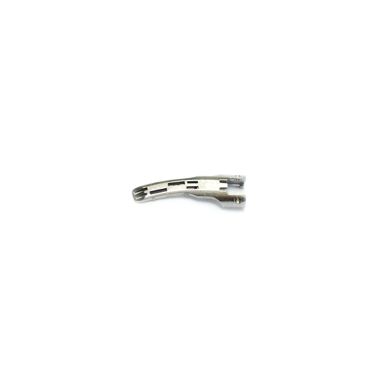
Ultrasonic Scalpel Blade Tip
Titanium ultrasonic scalpel blade tips built to drawing for surgical handpiece OEMs, with...
View Details →