Micro Bevel Gears
Mechanical Components
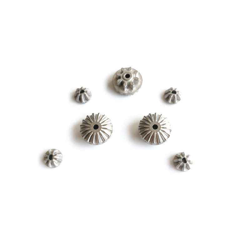
Micro bevel gears from module 0.2 to 1.5 mm produced by metal injection molding in 17-4PH, 316L and Fe-2Ni, with the shaft, D flat and bore formed in the same shot.
| Category | Mechanical Components |
| Materials | 17-4PH, 316L, Fe-2Ni, 420 Stainless, Ti-6Al-4V |
| Industries | Medical, Robotics, Automotive, Industrial, Consumer Electronics |
Send your drawing or 3D model — engineering review and quotation within 24 hours.
Yujiaxin Tech produces micro bevel gears by metal injection molding, in the module range where a cut bevel gear becomes difficult to hold and difficult to inspect. The tooth form, the shaft, the D flat and the bore are formed in the same shot, so a small right angle drive that would otherwise need four parts and three assembly steps can arrive as one component.
Why micro bevel gears suit metal injection molding
A bevel tooth is a three dimensional form that varies along its length. At module 0.5 and below, holding that form with a cutter means a very small tool, a very light depth of cut and a fixture that can index the blank accurately. The smaller the gear, the worse the economics get.
Metal injection molding, usually shortened to MIM, avoids the cutter entirely. The tooth cavity is cut into the tool once, at a size that a toolmaker can work comfortably, and every part after that is a copy of the cavity. The same shot fills the shaft, the flange, the keyway and the bore, which is where the route earns its place on a micro bevel gear rather than on a simple spur gear.
The trade is accuracy and density. A molded tooth does not reach the grade of a ground bevel tooth, and the sintering shrinkage has to be managed across the whole section. Both are predictable in a stable process, and both belong in the drawing conversation before tooling starts.
The MIM route in five steps
- Feedstock: fine metal powder at 10 to 20 um is mixed with a wax or polymer binder at 55 to 65 percent powder loading by volume
- Injection: the feedstock is injected into a hardened steel tool at 150 to 190 C, and the part shrinks as it cools, so the cavity is cut oversize
- Debinding: the binder is removed by solvent, catalytic or thermal route, leaving a porous brown part that is still handleable
- Sintering: the part is fired at 1200 to 1350 C in a controlled atmosphere and shrinks 15 to 20 percent linearly as it densifies to 96 to 99 percent of theoretical
- Finishing: hardening, coining, a light cut on the bore or a passivation step, chosen to match the duty and the tolerance
Bevel geometry we can form
| Type | Status | Notes |
|---|---|---|
| Straight bevel, 90 degree shaft angle | Standard | The shape where molding is most predictable and tooling cost is lowest |
| Straight bevel, non 90 degree angle | Standard | Angle is set in the cavity, no extra operation |
| Zerol bevel | Case by case | Reviewed against the parting line before quotation |
| Spiral bevel | Case by case | Needs a rotating ejection or a split cavity, so tooling cost rises sharply |
| Internal bevel and face gear | Standard | Often the reason a design moves to molding in the first place |
An integral shaft is the feature that changes the cost balance most. A bevel gear molded onto a 2 mm shaft with a D flat and a shoulder replaces a pressed and pinned assembly, and it removes the runout stack that comes with it.
Materials we mold
| Material | Sintered density | Typical use | Notes |
|---|---|---|---|
| 17-4PH stainless | 7.6 to 7.75 g/cm3 | General micro drives | H900 condition gives about 40 HRC with good corrosion resistance |
| 316L stainless | 7.7 to 7.9 g/cm3 | Wet and medical housings | Corrosion first, strength second |
| Fe-2Ni low alloy | 7.4 to 7.6 g/cm3 | Loaded gear trains | Case hardenable to 55 HRC at the surface, tough core |
| 420 stainless | 7.5 to 7.7 g/cm3 | Wear resistance | Hardenable through the tooth, used where sliding wear dominates |
| Ti-6Al-4V | 4.3 to 4.4 g/cm3 | Weight critical assemblies | Low mass, lower modulus, needs care at the tooth root |
Typical specifications
| Parameter | Range |
|---|---|
| Module | 0.2 mm to 1.5 mm |
| Outer diameter | 3 mm to 25 mm |
| Tooth count | 8 to 60 |
| Shaft angle | 90 degrees standard, other angles to drawing |
| Integral shaft diameter | 1 mm to 8 mm |
| Sintered density | 96 to 99 percent of theoretical |
| General tolerance | plus or minus 0.3 percent, floor of plus or minus 0.05 mm |
| Tooth accuracy | DIN 9 to 10 as molded, DIN 8 after coining |
| Bore tolerance | H7 after sizing or a light cut |
| Hardness | As sintered, or 30 to 55 HRC after heat treatment |
| Inspection | Density, tooth thickness over pins, runout, contact pattern, hardness |
Where molding stops and cutting takes over
Three conditions send a micro bevel gear back to a cut or ground route, and it is worth checking them before a drawing is finalized.
The first is accuracy class. If the drive needs a ground tooth at DIN 6 or better, molding gets close but does not reach it, and a coining step only recovers part of the gap.
The second is load. A molded tooth at 97 percent density behaves close to wrought material in compression but carries less root bending capacity than a forged and cut tooth of the same section, so a bevel pair that sees shock loading should be checked against molded properties rather than handbook steel values.
The third is volume. Tooling is a fixed cost that sits in the piece price at low quantity. MIM becomes competitive from roughly 5,000 to 10,000 pieces a year upward, and below that a cut gear from a standard range is usually the better buy. We will tell you when the volume does not support tooling rather than quote a part that will not pay back.
Accuracy, inspection and documentation
Tooth thickness is measured over pins and compared against the theoretical value for the molded pressure angle, because a bevel tooth does not lend itself to a simple span measurement.
Contact pattern is checked on a matched pair at the specified mounting distance. This is the check that matters most on a bevel pair, since two parts can each measure inside tolerance and still run on the toe or the heel of the tooth.
Each lot ships with a material certificate, the measured sintered density, a dimensional report and the hardness result. Where a customer needs a first article inspection to their own form, we complete it before the production run.
We hold ISO 9001 and GJB 9001C-2017. All gears are supplied as components for OEM assembly, not as finished machinery.
Applications
- Micro gearmotors and right angle reduction heads
- Servo and actuator gear trains in robotics
- Surgical instrument drives and dental handpiece assemblies
- Automotive mirror, headlamp and seat adjuster units
- Flow meters and dosing pumps with a vertical drive
- Camera, lock and small appliance mechanisms
What to send for a quotation
A drawing of the gear, or of the assembly it sits in, is the fastest route to a firm price. When a drawing is not ready, the following is enough for a first reply.
- Module, tooth count and outer diameter
- Shaft angle and the mounting distance for the mating gear
- Pitch cone distance and face width
- Material, or the load and environment the part sees
- Features to be molded in the same shot, such as shaft, flat, bore or flange
- Accuracy grade and the tolerances that matter most
- Heat treatment or surface finish, if any
- Annual volume and the expected order pattern
Send those eight items and we reply with a price, a tooling cost and a drawing for approval within 24 hours. Where the geometry needs a split cavity or a rotating ejection, we say so at quotation stage rather than after the tool is cut.
FAQ
Can metal injection molding hold a bevel tooth at module 0.3?
Yes, and that is close to where the route is most useful. The tooth cavity is cut oversize in the tool to allow for 15 to 20 percent linear shrinkage, and the molded tooth lands at DIN 9 to 10. A coining step can bring the pair to DIN 8 where the drawing needs it.
Can the gear and the shaft be molded as one part?
Yes, and it is usually the main reason to choose the route. A bevel gear molded onto a shaft with a D flat and a shoulder removes a press fit, a pin and the runout that comes with them. Any feature that would trap the part in the die has to be redesigned or left to a secondary operation.
What is the minimum order for a new micro bevel gear?
Tooling is the constraint rather than the press. We quote from roughly 5,000 pieces a year upward, and below that the tooling cost usually dominates the piece price. Trial batches can be run from the same tool once it exists.
Can you match a bevel gear from an existing gearmotor?
Often. Send the part number, a photo of the pair and the measured mounting distance, and we will confirm whether the geometry suits a standard cavity or needs a new tool. Where the original drawing is unavailable, we measure the sample and send a drawing for approval before cutting the tool.
Related pages
Browse the full mechanical components range, compare our miniature precision gears, powder metallurgy gears and high precision worm gear and worm wheel, review the materials we work with, or send us your drawing for a micro bevel gear quotation.
More in Mechanical Components
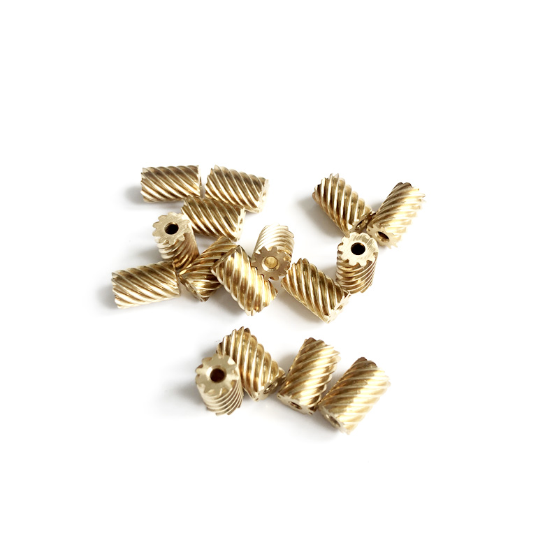
Small Module Multi-Start Worms
Small module multi-start worm shafts machined on CNC turning and whirling centres, module 0.2 mm...
View Details →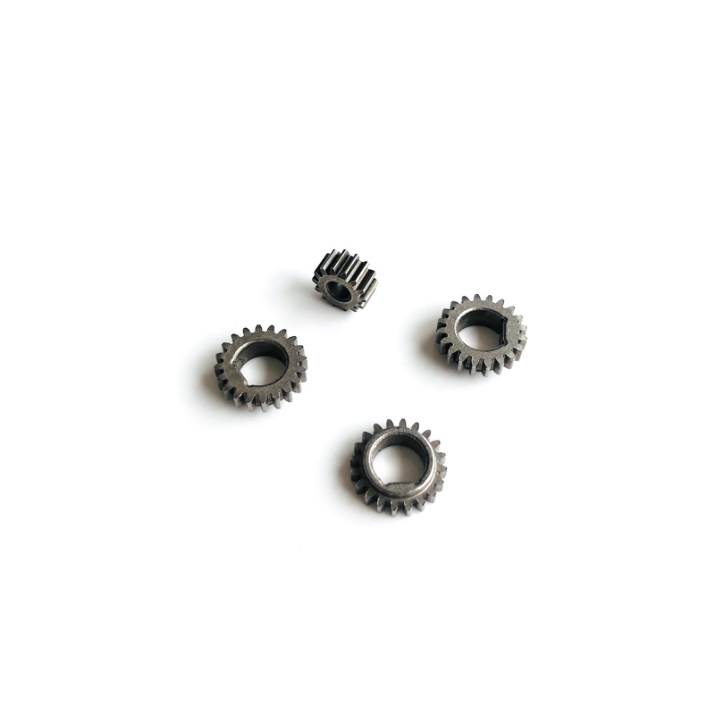
Powder Metallurgy Gears
Powder metallurgy gears pressed and sintered in iron copper carbon steel and stainless steel,...
View Details →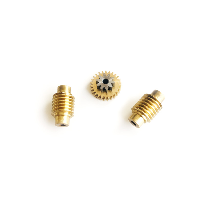
High Precision Worm Gear and Worm Wheel
High precision worm gear and worm wheel pairs in bronze, hardened steel and stainless steel,...
View Details →