High Precision Worm Gear and Worm Wheel
Mechanical Components
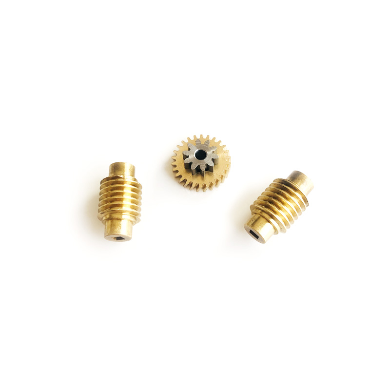
High precision worm gear and worm wheel pairs in bronze, hardened steel and stainless steel, supplied as matched sets with ratio, center distance and backlash confirmed to your drawing.
| Category | Mechanical Components |
| Materials | Bronze CuSn12, Aluminium Bronze CuAl10Fe3, 42CrMo, 20CrMnTi, Stainless Steel 303, Brass H62 |
| Industries | Industrial, Automation, Automotive, Medical, Consumer Electronics |
Send your drawing or 3D model — engineering review and quotation within 24 hours.
Yujiaxin Tech supplies high precision worm gear and worm wheel pairs as matched sets. The worm shaft and the wheel are quoted together, so ratio, center distance and lead angle stay consistent instead of being reconciled later from two suppliers. Each pair is made to the customer drawing and inspected as an assembly before it leaves the plant.
Why a worm gear pair suits right angle reduction
A worm gear set takes the input at 90 degrees and delivers a large reduction in a single stage. That removes a bevel stage and a planetary stage from many compact designs, which shortens the housing and lowers the part count.
The sliding contact between the worm thread and the wheel tooth is what makes a single stage ratio possible at all. It is also what sets the limits. Efficiency, heat generation and lubrication all follow from that sliding action, so a high precision worm gear pair has to be specified as a system rather than as two separate parts bought to two separate drawings.
Ratio, starts and lead angle
Ratio is the number of wheel teeth divided by the number of worm starts, not by the number of visible threads. A single start worm against a 40 tooth wheel gives 40:1. The same wheel with a two start worm gives 20:1 and a steeper lead angle.
- Single start: highest reduction, lowest lead angle, the highest chance of holding position under load
- Two or three start: faster output, higher efficiency, less holding effect
- Four start and above: chosen when output speed matters more than holding torque
Lead angle also decides whether the drive can be back driven. Below roughly 5 degrees a pair usually holds its position when the motor is off, which is why worm drives appear in lifting, positioning and door hardware. A buyer who needs the output to turn by hand should specify a multi start worm from the start rather than discover the constraint at prototype stage.
Materials we pair
| Worm shaft | Worm wheel rim | Typical use | Notes |
|---|---|---|---|
| Hardened steel 42CrMo | Bronze CuSn12 | General reduction units | A hardened thread running against bronze is the standard pairing for long life |
| Case hardened steel 20CrMnTi | Aluminium bronze CuAl10Fe3 | High load and shock | Higher load capacity, needs a reliable oil supply |
| Stainless steel 303 or 316 | Bronze CuSn12 | Wet or wash down areas | Corrosion resistance with a known wear couple |
| Brass H62 | Brass H62 | Light duty instruments | Quiet running at low load and low cost |
The worm wheel is normally a two piece assembly, a bronze rim on a steel or cast iron hub. That keeps bronze only where the sliding contact happens and lets the hub carry the torque. A solid bronze worm wheel is fine for small modules, but above roughly 60 mm diameter the two piece build is usually cheaper at the same rating. Each pair carries one assembly number, so a worm wheel and a worm shaft from different sets cannot be mixed in stores.
Typical specifications
| Parameter | Range |
|---|---|
| Axial module | 0.3 mm to 4 mm |
| Worm wheel teeth | 15 to 120 |
| Worm starts | 1 to 4 |
| Ratio | 5:1 to 100:1 |
| Lead angle | 2 to 25 degrees |
| Center distance | 8 mm to 120 mm |
| Accuracy grade | DIN 7 to DIN 9 |
| Thread hardness | 45 to 58 HRC, through hardened or case hardened |
| Thread surface finish | Ra 0.4 to 0.8 um |
| Inspection | Profile, lead, backlash, contact pattern, runout |
| Documentation | Material certificate, dimensional report, contact pattern photo |
What a worm drive changes in your design
Three properties usually decide whether a worm pair fits a design: reduction per stage, holding behaviour, and the direction of the thrust load.
Thrust appears on the worm shaft as well as on the worm wheel, so bearing choice on both shafts has to be settled before the housing is drawn. A pair that runs quietly on a bench can still be noisy in the assembly if the worm is allowed to float axially.
Heat is the other constraint. Losses in a worm mesh are higher than in a parallel shaft mesh at the same ratio, so a small housing may need fins or a larger oil volume rather than a different gear set. If the duty cycle is continuous, tell us the running hours and the ambient temperature, because those two numbers change the recommendation more than the torque figure does.
Accuracy, inspection and documentation
We inspect the pair, not only the individual parts. Backlash and contact pattern are measured with the worm and wheel mounted at the specified center distance, because a contact pattern checked on a single part tells you very little about how the pair will run.
The report covers profile and lead deviation on the worm thread, tooth thickness and runout on the wheel, plus the measured backlash at the quoted center distance. A contact pattern photograph is included, so the assembly line can compare what they see against what we measured.
We hold ISO 9001 and GJB 9001C-2017. All worm gear pairs are supplied as components for OEM assembly, not as finished machinery, and the declared accuracy grade refers to the pair as measured at the quoted center distance.
Applications
- Right angle worm gear reduction units and compact gearmotors
- Positioning stages, valve actuators and damper drives
- Medical and laboratory equipment where a holding ratio is useful
- Automotive seat, window and mirror adjusters at small module
- Industrial door and gate hardware with a manual release
- Packing and labelling machinery with a vertical output shaft
What to send for a quotation
A drawing of the pair is the fastest route. When a drawing is not available yet, the following is enough for a firm reply.
- Ratio, or worm wheel teeth and worm starts
- Center distance and the mounting arrangement for both shafts
- Module or the measured diameter over the worm thread
- Material for the worm and for the wheel rim
- Accuracy grade and the backlash you can accept
- Input speed, output torque and duty cycle
- Whether the pair must hold position with the motor off
- Quantity for the first order and the expected annual volume
Send those eight items and we reply with a quotation and a drawing for approval within 24 hours. Samples for a first article check are available before a production order, and we can supply the wheel and the worm as separate part numbers when your assembly line prefers to keep them apart.
FAQ
Can you supply the worm shaft and the wheel as one matched set?
Yes, and for this drive type it is the better way to buy. Backlash, center distance and lead angle are properties of the pair, so quoting both parts together removes the risk of two suppliers working to slightly different reference dimensions.
What is the smallest module you can hold on a worm thread?
Axial module 0.3 is practical in hardened steel. Below that the thread flank gets thin enough that lead measurement becomes unreliable with standard equipment, so we review any smaller drawing before committing to a tolerance.
Can the pair be made to hold position when the motor is off?
Usually yes, with a single start worm and a lead angle below about 5 degrees. The exact point depends on the friction couple and on vibration in service, so we quote holding behaviour as a design intent rather than as a brake rating.
Can you match an existing gearbox part number?
Often. Send the part number, a photo of the pair and the measured center distance, and we will confirm whether the geometry matches a standard build or needs a new drawing. Where the original drawing is unavailable, we reverse the dimensions from the sample and send a drawing for approval before production.
Related pages
Browse the full mechanical components range, compare our miniature precision gears and brass miniature helical gears, review the materials we work with, or send us your drawing for a high precision worm gear quotation.
More in Mechanical Components
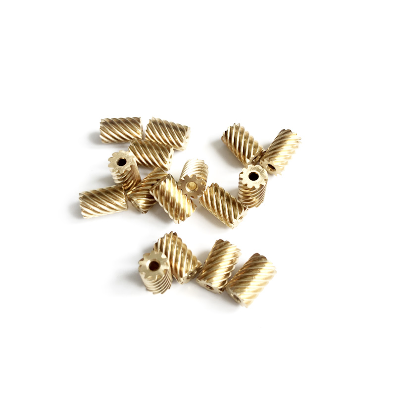
Small Module Multi-Start Worms
Small module multi-start worm shafts machined on CNC turning and whirling centres, module 0.2 mm...
View Details →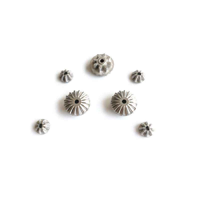
Micro Bevel Gears
Micro bevel gears from module 0.2 to 1.5 mm produced by metal injection molding in 17-4PH, 316L...
View Details →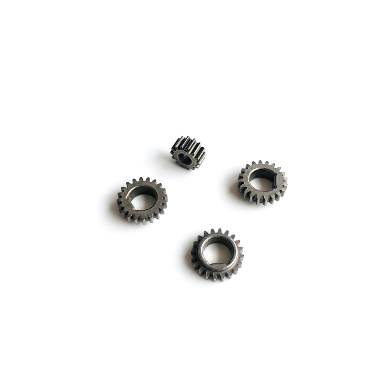
Powder Metallurgy Gears
Powder metallurgy gears pressed and sintered in iron copper carbon steel and stainless steel,...
View Details →